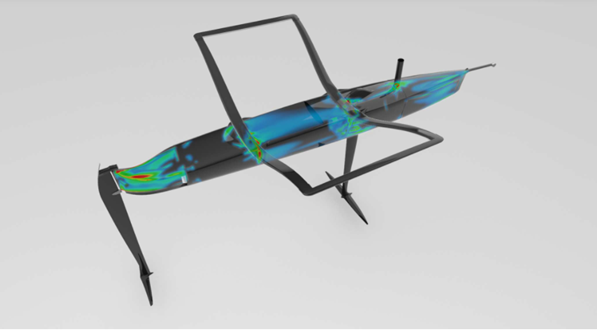
Despite the widespread availability of this technology it is seldom used to its maximum benefits. Yet the motivation to use optimization is compelling and in mechanical applications which we are focusing on here, weight saving and/or stiffness increase can be achieved without sacrificing the safety of the structure.
There are different types of optimization available, depending on the development stage, design freedom and objectives. With Paul's almost emotional connection to structural design it was obvious that we had to transfer these methods from the America’s Cup into the Moth project. Once the decision was made to take this path, we took step after step from the conceptual design to the final detailing, using suitable and different optimization types in every stage.
Setting up the problem
One of the advantages of numerical optimization is the simultaneously consideration of multiple load cases including varying loads and boundary conditions. In figure 1 the main load cases considered in the optimization process are shown. One can easily imagine that a designer is capable of focusing on one load case and get reasonable solutions for strength and stiffness, but simultaneously focusing on all load cases is an impossible task. Here the computer is a great help!
Figure 1

First Step - Sizing
The first optimization task we tackled was the geometric sizing of the rack. What is the optimum aspect ratio of the rack beams and how are these distributed to achieve maximum stiffness without breaking. As the objective is minimum weight, the optimizer was allowed to modify rack beam height. In Figure 2 we see the configuration before and after the optimization. It then needed Paul's expertise – and therefore still some human inspiration – to interpret these results and combine this with other design requirements of the Moth (ergonomics, aerodynamic drag, fitting positions, etc)
Figure 2

Detailing - Laminate Scantling
Next step in the optimisation process is the property or thickness optimisation. Here laminate thicknesses, layer orientation and material types are optimised again under the objective of minimum weight. The optimisation delivers for example a distribution of the unidirectional fibres in a preselected high modulus material (it also reveals the layup for the other directions). Figure 3 shows such a distribution across the rack.
Figure 3

Final Step - Validation
The optimisation process shown here (for the rack structure) is only a typical extract of what we have undertaken on the rest of the boat. Hull, rudder, main foil, etc. underwent a similar procedure with the objectives individually set in each case (weight, deflection, etc.)
As on other projects, the final step is checking the structural response of the Moth with every detail incorporated in it. Figure 4 is showing the stress envelope on the current rack and hull over all loadcases – a very evenly distributed stress distribution pointsto a very efficient structure.
Figure 4

The methodologies described here are readily available – all that is required are designers willing to incorporate them into the design process...
Leopold Fricke and Thomas Hahn, iXent, Munich

